In a Sales Bulletin dated November 29, 1995, Icom officially says: "OUT-OF-BAND RECEIVE MODIFICATION "A factory approved receive modification is enclosed. It's very simple, just cut the yellow wire (of course wire colors may change in the future, so it's best to locate the proper wire with the schematic drwaingt, just to be safe. "This modification substantially improves the FM VHF out-of-band receive performance. However, you may notice some diminished sensitivity on VHF WFM broadcasts. "An HF MARS trsnsmit modification is also attached. No approved VHF transmit is available at this time. We are working on it."
Another paragraph says: "HM77 DTMF Microphone" "We have received many requests for a DTMF microphone. After extensive testing, we feel the HM77 is your best choice. The transmit audio soinds a bit different to some observers." (Note - the HMN77 should be available at Icom dealers in the near future .. at the time Icom distributed this Sales Bulletin, they did not even have a price on the HM-77! It is now priced, and should be available soon.)
Please note that these notes are typed verbatim from the Icom Sales Bulletin - typos are theirs, not mine.
73 to all,
"Squeak" Porray, AD7K Manager, Amateur Electronic Supply/Las Vegas
-------------------------------
Re: ICOM 706 Reports
I have had mine since the day before Thanksgiving and offer the following comments:
The radio basicly does everything claimed quite well. Past comments in this newsgroup are pretty much on target. The nitpickers will complain about high speed QSK, the tinny sounding speaker and a few other shortcomings, but on balance I believe that ICOM has created a radio that will see a very high level of market acceptance.
I am using my radio for auto and sailboat mobile operation and feel that it performs that task very well. I have no substantial complaints about the radio and would make the same decision again (in fact my brother went out and bought one the next day after seeing mine on Thanksgiving day).
Regards,
Howard N7TI
-------------------------------
-- Howard Radke - N7TI radke@radke.seanet.com
For those who don't want to cut the yellow wire, the pin can be left on the yellow wire and returned to its normal state later if you want to un-mod the radio. Simply unplug the connector. Using a paper clip, push in on the release pin on the side of the connector while tugging n the yellow wire. The pin will come right out. Now you may wrap a small wire around the neck of the pin, solder then tape it. Run the extension down to the vco point. --- Steve Ellington N4LQ@IGLOU.COM Louisville, Ky
-------------------------------
ICOM-706 MODIFICATIONS As of Dec. 9, 1995
SUMMARY -------
MODIFICATION 1: Enables extended transmit from 1.6 to 54 MHz inclusive. MODIFICATION 2: Enables extended receive from .05 to about 165 MHz inclusive.
CAUTION
-------
Improperly performed modifications can severely damage your radio. Use extreme caution. Proceed at your own risk.
Transmitting on frequencies other than those assigned to the amateur radio service may be illegal.
TOOLS RECOMMENDED
-----------------
1) Small philips-head screwdriver
2) Magnifying glass
3) Small wattage (15 watt) soldering iron with a small tip
4) Long-nosed pliers
5) Paper clip
6) Tweezers
MODIFICATION 1
--------------
Result of modification: The IC-706 transmits only on the ham bands. This modification allows for transmit on any frequency from 1.6 to 54 MHz. The radio will also continue to transmit on 2 meters (144 to 148 MHz in the United States) at 10 watts output. This modification will NOT allow for transmit on the AM or FM broadcast bands. The radio will appear to transmit on most frequencies above 54 MHz, but the power output will be a milliwatt or less. The highest power output will be 100 watts from 1.6 to 54 MHz (SSB, FM, CW; 40 watts AM) and 10 watts on 2 meters. (SSB, FM, CW; 4 watts AM) Note: This modification requires that you reset the CPU. All memory information will be erased.
1) Disconnect the power cable. Open the TOP cover of the radio. You will need to remove only 5 screws: three on the top of the radio and one screw on each side. Pull up the speaker carefully and set it aside. Look at the radio from the front; the speaker area should be in front.
2) Locate the rectangular, silver 9 MHz SSB filter. This is clearly marked on the top of it. Now look to the right. Note the "D 108" marking. Below this marking, there are three tiny black diodes. There are two diodes, followed by two blank sockets, followed by another diode.
3) The second diode from the left (the middle diode) is diode D-59. This diode needs to be removed. There are many ways to remove this diode. The easiest way is to crush it with long-nosed pliers. Another way is to use a low-wattage soldering iron and tweezers and carefully heat the diode, then pull with the tweezers. Be extremely careful not to apply too much heat.
4) Re-assemble the radio. Press and hold the UP and DOWN buttons on the right side of the front panel, and while holding them down, turn on the power. This resets the CPU.
MODIFICATION 2
--------------
Result of modification: The bandpass filters on the IC-706 are improperly wired. As a result, the radio does not receive any stations above 129 MHz, except in the 2-meter band. This modification allows for reception up to about 165 MHz.
(Note: If your radio receives the FM broadcast band (88-108 MHz), the aircraft band (108-136 MHz), 2 meters, and stations above 148 MHz, it is possible that the modification has already been performed by Icom; you may have a later model.)
1) Open the TOP cover of the radio. You will need to remove only 5 screws: three on the back of the radio and one screw on each side. Pull up the speaker carefully and set it aside. Look at the radio from the front; the speaker area should be in front.
2) Locate the rectangular, silver 9 MHz SSB filter. This is clearly marked on the top of it. Now move your eyes toward the back of the radio until you notice a long white connector with several colored wires on it.
3) The 4th wire from the left, a yellow wire, needs to be removed from the connector. You can cut this wire carefully if you wish. Or, another alternaive is to remove it from the connector. Stick a paper clip or perhaps a pin into the side of the connector under the yellow wire. Pull the wire with tweezers and remove it. There are two yellow wires; be sure to remove the 4th wire from the left, not the other one.
4) Open the BOTTOM of the radio, removing similar screws as you did when you removed the TOP.
5) Look at the PC board just behind the MENU button. You will notice a jack marked "J8" with a grey cable coming out of it.
6) To the left of jack J8, you will see five tiny transistors. Look at the middle transistor. Follow the light green circuit board trace from the middle transistor to a tiny hole just to the left of J9.
7) The yellow wire from the top of the radio needs to be connected to this transistor. The easiest way is to solder a small insulated wire to the yellow wire you just removed, run this new wire underneath the radio to the hole you found in #6 above, put the wire into the hole, and solder the wire into the hole with a low-wattage soldering iron. Use caution not to damage the grey cable or to apply too much heat. This could damage the PCB and seriously affect the radio.
If you perform only steps 1 through 3, you will be able to hear stations above 148 MHz, but you will not be able to hear FM broadcast stations on the 88-108 MHz band.
RECEPTION SUGGESTIONS
---------------------
1) You need to use wide FM to receive FM broadcast signals on the 88-108 MHz band, or TV sound signals between 59 and 87 MHz. To receive wide FM, press the MODE button until "FM" or "FM-T" appears on the display, then press and hold the MODE button for two seconds. "WFM" should now appear on the display, and you should be able to hear the FM broadcast stations. Reception quality is quite good if you use a decent external speaker.
2) Aircraft (118-136 MHz) uses AM. You will need to set the radio to AM to receive aircraft.
3) The sensitivity of the radio diminishes rapidly after about 165 MHz. NOAA weather stations (162.40 to 162.55) are clearly audible, however.
4) If you find the FM broadcast signals overload the aircraft portion of the bands, disable the preampifier by pressing PREAMP (the green light should go out.)
08 Dec 1995 From Paul Nix (WB5AGF) (e-mail: Paul_N_Nix@aud.alcatel.com)
-------------------------------
ICOM-706 Technical Information
==============================
Purpose
-------
I've been reading an awful lot the last 2 - 3 weeks about people modifying their brand new ICOM IC-706 radios. Having bought an IC-706 myself a couple of weeks ago, details regarding 'enhancements' to IC-706's have taken on a new interest.
It's clear that few, if any, hams have a schematic of the IC-706, and that's where I may have some useful information; I DO HAVE A SCHEMATIC (although a bit 'blurry' in some areas), and think that some circuit details may be of interest.
No ... I don't plan to provide a written description of the whole radio; there's a lot of the circuitry that I haven't even figured out what it does yet. What I DO have is some information relating to the 'front-end' filtering used above 60 MHz, and details regarding the synthesizer.
As I understand other circuit details, I may post more information.
Disclaimer
----------
'The usual'; ie. use at your own risk, your mileage may vary, no user serviceable parts, etc. And no, I have no connection with ICOM, except for helping improve their 'bottom-line' with my purchase of a IC-706. I'm writing this 'after-hours', so my employer will 'disavow- all-knowlege' if you ask them.
Philosophical Ramblings
-----------------------
If the truth be told, I'm a dyed-in-the-wool Drake and Tentec man (I still have my R-4B receiver circa 1967, T-4X transmitter from 1970, and 1988 Paragon transceiver).
So why 'switch' you ask? Real simple (and I don't view it as 'switch- ing', just 'adding'), the IC-706 is just too doggone 'neat' to pass- up. Where else can you hold an entire 100 Watt HF/6M rig in your lap, plus 10 Watts for 2 Meters? Laugh if you will, but I'm convinced the IC-706 is composed of 1 part 'Rocket Science' and 1 part 'Magic'. They didn't tell me about this stuff when I was getting my EE degree back in the late 1970's (ie. the 'Stone Age').
Of course there is a 'down-side'. Whereas I can work on my Drake and Tentec gear, there's no way my pudgy fingers will ever have the dexterity (or my ageing eyes the clarity) required to do anything other than the most trivial surface-mount work. Looking at the IC-706's circuitry and I'm wondering "Is that a transistor?!". Robert A. Heinlein invented (far as I know) the expression "TANSTAAFL" ('There ain't no such thing as a free lunch'). With the stunningly small size of the IC-706 comes the shattering realization that I'm not able to maintain the radio (rats!).
Receiver Front-End Filtering, 60 - 200 MHz ------------------------------------------
The IC-706's receiver front-end filtering above 60 MHz is rather simple. Coming in from the antenna there's a low-pass filter, which's shared by the transmit signal path (I've done no calculations yet on that filter). After that we come to the following two possibilities.
When the radio is operating on the 2 Meter Band (144 - 148 in the U.S.) a bandpass filter is in-line. It consists of a two singly- tuned transformers, with a 0.79 pF coupling capacitor between them. (Can there really be that small a capacitor? Sounds more like 'stray' coupling than a discrete component, but the schematic shows it as an actual part) The schematic provides no tuning or alignment data, so I must assume that ICOM has the coupling capacitor, and transformer tuning, set for slight over-coupling, to produce a somewhat 'flat- topped' response across the 2 Meter Band.
ANYWHERE OUTSIDE THE 2 METER BAND (this only applies above 60 MHz of course), and the 'filtering' consists of a low-pass/high-pass filter combination. I'm certainly not a 'modern filter' design theorist. I can figure basic Poles & Zeros, but not much beyond that.
Several people have reported the IC-706's receiver sensitivity dropping-off rather abruptly up around 165 MHz. When I squinted really hard at the schematic (6's and 8's tend to blur together), and 'punched some numbers' into my little calculator, here are some of the figures that I got:
Coming in from the antenna, the receive signal hits a parallel LC pair (82 nH & 12 pF); I figure there's a Pole at 160.44 MHz. There are also 20 pF cap's, on either side of this section, going to ground, but I don't know how to 'handle' them. (Yea, I know it's some sort of Cauer/elliptic filter, but that's all)
Next the signal goes to a parallel LC section of 68 nH and 20 pF, that I believe produces a Pole at 136.47 MHz. There's either a 10 or an 18 pF capacitor on the output (leaving this LC section), but the schematic's too blurry to make out which.
Now the signal hits the high-pass filter section. In series there are capacitors of 24, 22 and 27 pF. Between the 24 and 22 pF caps is a series LC circuit to ground of 220 pF and 0.15 uH, although the inductor's figure is very hard to read. My calculator tells me that series resonance (a Zero) should occur at 27.71 MHz. Then, between the 22 and 27 pF capacitors, there's a series LC of 82 pF and 0.18 uH, which should produce a Zero at 41.43 MHz.
Logically, the result of this low-pass/high-pass filter would seem to be a response that falls off rather quickly somewhere a bit above 41 MHz (the upper of the Zeros in the high-pass section) as you move down in frequency, and somewhat below 136 MHz (the lower of the Poles in the low-pass section) as you go up in frequency.
Once the receive signal gets through either the 2 Meter bandpass filter, or the 'everywhere-else' low-pass/high-pass filters, it goes to a preamp, followed by a low-pass filter (I haven't tried to work-out its characteristics yet). It appears that it's right at that preamp that the 60 - 200 MHz receive signals 'meet-up' with the signal flow that's followed by the HF and 6 Meter signals. Those signals have gotten to the preamp via a completely different path, but I won't cover that now.
Some Very Simple Synthesizer Comments
-------------------------------------
The "yellow wire" modification, much talked-about, seems to have an 'advanced-option', where some brave persons have managed to pick-up a control voltage on a tiny surface-mount transistor on the synth- esizer board. In the discussions on this subject, it appears that there is a misconception about what that transistor does.
The IC-706's synthesizer uses (among other things) two VCO's. The two VCO's can have either their direct output used, or there is also a frequency doubler circuit available. "VCO 0" (zero) is used on its fundamental up to 29.999999 MHz. At 30.000000 MHz "VCO 1" takes over, and is used up to 59.999999 MHz. At 60.000000 MHz, "VCO 0" takes over again, but goes through the doubler circuit. "VCO 0", with its freq- uency doubled, works up to 128.999999 MHz. At 130.000000 MHz, "VCO 1" takes over again, this time with its frequency doubled, and that's what's used up to the 200.000000 MHz upper-frequency limit of the IC-706.
Now, the output of these VCO's, either the fundamentals, or the first harmonic (2 X fundamental), go through a bank of filters (the IC-706 is 'oozing filters'; they're all over the place). Between 0.03 MHz and 29.999999 MHz, a low-pass filter is used. Between 30.000000 and 59.999999 MHz, another low-pass filter cuts-in. Between 60.000 and 128.999999 MHz a high-pass/low-pass filter pair is used. Between 129.0000 and 143.999999 MHz ...AND BETWEEN 148.000001 and 200.00 MHz another high-pass/low-pass filter combination is used. BETWEEN 144.000000 and 148.000000 MHz, a separate band-pass/low-pass filter set-up is used.
It is because of this mixture of synthesizer output filters that people have been able to find that transistor, to hook the famous "yellow wire" to. That transistor is one of several, that switch the appropriate synthesizer output filters in-and-out of the circuit.
- End Of Discussion - Here are the results of a sensitivity test of my IC-706 for 60MHz<f<200MHz, both for the unmodified radio, and after performing the "yellow wire" modification. I used a Wavetek 3002 sig generator, a Kay switched attenuator, and made sure all impedances were 50 Ohms. Test Conditions: Mode-CW Filter-wide Preamp-Off
Signal levels in the table are the minimum level required to light the first bar on the s-meter. The minimum detectable signal was about 30-db lower than the indicated value. All signal strengths are in microvolts rms.
General Impression: Except for a slight decrease in sensistivity between 120-135MHz, the modified IC-706 has excellent sensitivity over the full frequency range, up to about 160MHz. Sensitivity rolls off sharply above 160MHz.
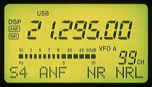
S-METER CALIBRATION: test conditions: preamp OFF freq:14.030MHz mode: CW Filter: wide
General Comments: The S-Meter is very poorly calibrated between S1-S9, with only a 17db difference required to turn an S1 signal into an S9 signal. Functionally, the S-meter is nearly worthless in this range, since its calibration is more nearly linear than logarithmic. For signals above S9, however, it is quite accurate.
Coming Soon: Results of selectivity measurements for the SSB and 500Hz filters.
Pricing Comments: I'll conclude with a small gripe. My XYL picked up the Y-adapter cord for me at the local ham store, yesterday, since the accessary connector on the back of the IC706 is a strange DIN-type connector I've never seen before. When she got home, I learned that the cost of the adapter cable was $45!!. In my opinion, Icom is gouging customers with this pricing schedule. I'd guess a reasonable retail price for the adapter cable (part no. OPC599) is aout $12. The power cord for the IC706 is $21, which is also far too high.
73,
-------------------------------
Jim W8ZR It is as if they had to WORK at it to make qsk this bad. My Kenwood TS-940 has been tested for qsk above 100wpm showing no effect on keying. The Ten Tec Hercules amp I use has a loud, large, reed relay for keying the final. It follows my keying to 50wpm with no noticible effects at all. The problem with the IC706 is that there is no weight adjustment for the internal keyer. It does have a "ratio" adjustment which indicates a range of from 2.8 to 3.?.... If 3:1 is the proper ratio, whats the deal with that Alinco rig and 2:1 sounding so good????? But ratio isn't the key factor here. Even if the ratio is correct, if your dots and dashes are clipped, it still stinks.
-------------------------------
This mod wrecked my ability to receive aircraft and the FM BCB.
You alsoneed to run a wire from your cut yellow wire to the PCB hole just to the left of jack J8 on the back of the rig. On the bottom PCB, you will see five tiny transistors located just behind the MENU button. Look at the middle transistor. Follow the trace from the transistor to the hole next to J8. You need to solder a wire to this hole, and run the wire over to the other side of the rig, and attach it to the yellow wire you cut. Then the rig will receive well on most of the VHF range (from 60 MHz up to about 162 MHz.)
Be very careful doing this. Use a low-wattage soldering iron and be careful not to damage any other wires or PCBs. I have tried this, and it works, but proceed at your own risk. An improper mod can damage the radio.
-- =-=-=-=-=-=-=-=-=-=-=-=-=-=-=-=-=-=-=-=-=-=-=-=-=-=-=-=-=-=-=-=-=-=-=-=-= Randall Rhea Systems Engineer Informix Software randall@informix.com
I've read the past 2+ months of archives on the IC-706. Surely one of the main problems is overly optimistic advertising. I haven't mod'ed mine, but offer the following analyses, mostly concerning reception on the FM BC band (the nearest FM BC station is about 9 miles distant):
> The WBFM IF bandwidth is something like 500 kHz with broad skirts, far far too wide to be useable in any major metropolitan area. The Baltimore / Washington area has many stations spaced 400 or even 200 kHz apart. There is no hope for the 706 to separate them.
> It is very common for FM stations to be spaced 10.4, 10.6, 10.8 or 11.0 MHz apart. The 10.7 MHz WBFM IF is so wide, and even moderately strong stations drive the rig into intermod, that this problem severely limits FM BC reception. OK, 10.6 and 10.8 MHz spacings must be quite a few miles apart.
> The WBFM first IF is at 70.7 MHz. The color subcarrier of my local TV channel 4 is at 70.8+ MHz, which is well within the WBFM IF.
> I have two pairs of FM BC stations, one of each pair about 10 miles away, the other 30 miles distant, where the spacing is exactly 9.0 MHz, the second IF frequency on all but WBFM.
I've added a high-pass 88 MHz filter with nulls at 70.8 and CH 4 and 5 video carriers; also a trap tuned to one strong local FM station. Now I can use the preamp above 120 MHz on the aircraft band and actually hear a weather station. The FM BC performance is still very unsatisfactory. Lots of intermod on FM BC, even with the attenuator switched in. I get the impression that the LO inject level may be inadequate.
Other than the above, resulting from the ads not matching reality, the 706 is a nice little rig.
73 be Bob w3otc
-------------------------------
This is the 50 Mhz and down Xmit Mod.
Caution: You will be working on a surface mounted, very small device. Be sure you have a strong magnifying glass and a strong bright light. To remove the device you will need a small soldering pencil and or dykes.
1. Place the radio front knob towards you and remove the top 3 and 2 side screws.
2. The main board is the one near the front.
3. The 706 has 5 diode spaces on this main board. These spaces are located just to the right of the orange ribbon cable connection and to the left of part R-198 marked on the circut board.
4. Now that you have found the 5 small spaces; you will see from left to right small 3 legged black diodes in positions 1, 2 and 5. On my US model diodes for spaces 3 and 4 are missing.
5. Next we want to remove unmarked diode D-59 which is the second diode from the left. You can use a small soldering pin or you might want to just cut it out of the way. I was able to unsolder the front two legs then raise the diode and unsolder the front leg.
6. Now your done ! Re set the CPU and you can transmitt below 50 Mhz. It works.
2nd Caution: If you are not comfortable working with very, very small devices find some one who is. This is too expensive a radio to screw up and trust me- it wont take much.
Removing this device (diode) might disable further mod's and will void your warranty. Thats another reason to unsolder and keep the diode. This mod works and I have noticed no side effects or strange problems. Now I can use this radio as a back up MARS Station.
73's Gary NI8K v-ntxes@microsoft.com (Eric E. Scott) wrote:
Give ICOM a call and they will send you a schematic for free. The service manual costs $30 dollars and is suppose to be out in January. -----------------------------------------------------
What John doesn't know is that we replaced the coffee he NORMALLY drinks, with a new, low-grade fiberglass. Let's see what happens...
The summary review of the '706 in the November issue of the French mag Radio-REF does not mention any reception between 60 and 118 MHz, nor does it mention the 70.7 MHz WBFM IF.
Back then it had not yet received the French equivalent of FCC type approval.
Perhaps the French authorities demand that FM broadcast receivers meet some reasonable minimum performance level...which the 706 certainly can't. On the ham bands, fine...but not on FM BC.
My 706 is on its way back to ICOM to see what they can do about the FM BC reception. Unless they can somehow reduce the intermod, I doubt that they will accomplish anything.
ICOM says I'm the only person who has complained to them about the FM BC reception.
73 de Bob Carpenter w3otc
-------------------------------
WB5AGF states that ICOM doesn't spec the 706 on the FM BC band. WRONG! Look on page 55 of the manual. Under WFM you will see "Less than 10.0 uV" "(for 12 dB SINAD)" and "*Some frequency ranges outside of the ham bands are not guaranteed." So, ICOM does spec the FM BC sensitivity, but does't guarantee it. In fact the bad intermod on FM BC makes this spec meaningless. My interest in have acceptable FM BC reception on the 706 is so that it could be the ONLY radio in my vehicle or boat (except for marine VHF on the boat). A single tuned trap at the VHF antenna connector, set experimentally to some strong FM station, brings the intermod to the point that my 706 is useable for FM BC. I assume I would need to retune the trap as I mobiled around town. If it had two FM BC IF filters of the 180-200 kHz width required by good engineering practice (not just one of 280 kHz plus with broad skirts), it wouldn't suffer so much QRM from adjacent channel stations. As for substituting the feature of synchronous AM detection for FM BC reception, I presume that the "features czar" at ICOM felt that FM BC would serve them better in a bells and whistles battle. 73 de Bob w3otc While ICOM may have designed the AT-180 for the IC-706, you will note that the 706 also carries a socket that allows direct connection of their AH-3 automatic tuner. The AH-3 is claimed to tune essentially any piece of wire, while the AT-180 can only hanadle a range of nearly-resonant antennas - as best I can read the specs. So, forget the AT-180; get an AH-3. Anyone have a good used AH-3 that I can buy??
Despite the miracle that is the IC-706, ICOM seems to have pulled a couple of boners in its design. 1) Not understanding(?) the non-ham VHF environment in North America and Europe has led them to accept a design which results in far too much intermod above 60 MHz (except where the "2 meter" front end filter can be used - see yellow-wire mod). 2) A similar lack of understanding has led them to choose a far-too-wide FM BC IF filter. Appropriate-bandwidth filters, with the same dimensions, are available from the same manufacturer that they use. Since most FM BC radios are made in the Far East and Japan, I'm surprised that ICOM's engineers were unaware of good engineering practice in the choice of the IF filter. Ah, but I've been seeking perfection. The 706 would still have been my choice even if I had I known of these problems before purchasing it. There is no competition for my uses: 100W up through 6m, all-mode 2m, general-coverage LF-MF-HF receiver with wide and narrow IF on AM, coverage to look for European TV below 6m, air-band coverage, 162 MHz weather coverage (with yellow-wire mod). A judiciously-tuned single L-C trap allows me to hear the FM BC stations that are most important to me. 73 de Bob w3otc
-----------------------------------
Above 60 MHz the IC-706 uses two different filters during receive. Inside the 2 Meter ham band there's a pair of transformers coupled by a very small capacitor. I think the circuit is probably tuned to act slightly overcoupled, to produce a 'flat-topped' response. When the radio's tuned outside the 2 Meter ham band, a 'lowpass- highpass' filter combination is used between 60 and 200 MHz. From some very rough calculations I've run, reading the component values off the schematic, and then punching them into my little hand calculator, it looks like that's going to provide a response somewhere between 45 and 125 MHz (there are "Poles" and "Zeros" in the filter response at roughly 41 and 130 MHz, so I'm guessing how far away the signal has to be to make it through the filter). The "yellow wire" modification apparently causes the radio to keep the 2 Meter filter in-circuit ANYTIME the receiver is tuned above 60 MHz. From the e-mail chatter I've seen, that apparently results in substantially increased sensitivity up to about 165 MHz, but the guys say the receiver overloads fairly easily. With my unmodified radio, I've noticed some pretty severe inter- ferance when listening to the commercial FM Broadcast Band here in the Dallas area. But don't forget, ICOM doesn't spec the receiver's performance above 30 MHz anywhere except INSIDE the 6 and 2 Meter Bands. Anywhere else is a 'freebie'. Concerning temperature
-------------------------------
I've only used my IC-706 on the HF bands, but it barely gets warm. That goofy little fan (inside the radio) runs all the time, and speeds up during transmit, but the radio, even given its tiny size, seems to have no problem coping with 100 Watt SSB transmissions. Matter of fact, I've become curious what kind of 'idling' current the output transistors are set to. The IC-706 uses Motorola RF FETs, and they may be much more efficient than the bipolar transistors that are used in older radios. Microphone Audio
-------------------------------
I have had some concern about that ... not that it's distorted, it's just that I can't get the ALC indication to reach the level that the manual talks about. The pattern I see on my old Heath HO-10 monitor scope looks good, so I'm trying not to let the meter reading concern me. If I cut the RF output back, which I believe just changes some parameters in the ALC control circuit, then I can 'push' the ALC indication to where the manual says it should be. The microphone provided with the radio has two rather strange metal and 'rubber' disks inside, actually blocking-off the 'grill', that make it appear as though the ICOM Engineers were trying to reduce the sensitivity. An ICOM Rep (Gary Fiber) suggested that I try removing the metal & rubber disks, to see if that would bring up the audio level. It may have helped a little, but I still run the IC-706 (when the RF transmit is set to "Hi") at the maximum (set in software) of "10". I do have a very soft voice, and many years of experience have shown that transmitter ALC circuits respond quite a bit less than when driven by more bassy voices. One thing that really bothers me, that nobody's talked about, the microphone PTT switch has this bizarre 'snap-action', that clicks so loudly that, when you unkey there's a very distinct RF 'spike' that goes out on the air (I see it on my monitor scope). If you run VOX (of course) you don't depress the PTT switch on the Mic, so no 'spike' is transmitted. I think that I'm going to try and change-out that switch, as that's just plain dumb design on the part of ICOM, and no excuse for it. I'm building an interface to allow me to use a Heil headset with the IC-706. When I called Heil, to get their opinion as to what needed to be done, the lady there commented that they've had problems with low audio when connecting to other ICOM radios, so I'm building up a little audio amplifier (took it out of the ARRL Handbook), to go into the adaptor box, to allow me to include a bit of gain if needed. 73 Paul Nix (WB5AGF) e-mail:
I found the AT180 (the tuner specifically for the IC706) a bit problematic. There are two small switches (inside the tuner, of course) which alter it's behavior. If your SWR is 3:1 or less at the tuner OUTPUT, the tuner is quite well behaved and automatic. If your SWR is higher, you get to change the switches and use a different front panel procedure to activate the tuner. (this requires opening the tuner, changing switches, and power cycling it). I can see no valid reason for these different modes - the tuner should just do "best possible job" and be done with it. Also on 6 meters (the band you specifically asked about) the tuner has a much narrower tolerance for mis- match - antenna SWR >3 or 4:1 will result in the tuner not staying online at all, and the activation procedure (how you operate the tuner from the front panel of the IC706 is different - read the manual!). All in all I think ICOM did a very poor job designing the AT180, particularly given it's price.
I E-Mailed Icom (don't have the address handy), and they graciously sent the schematic. They said they had some copied at a local copy house. There may be a limited supply. It is a LOT of paper. I got the address from the ICOM page on the WWW.
It's the famous "yellow wire" mod. When you take off the top cover, you'll notice a connector in the center of the radio with a number of colored wires coming from it. The 4th from the left is a yellow wire. Remove it from the connector. That will improve receive above 148 MHz. Unfortunately it trashes receive below 120 MHz (on VHF, this mod has no effect on HF). So you have to do one more step. Turn the radio over and remove the bottom cover. At the front edge of the circuit board, you'll see 5 tiny SMD transistors. There's a trace coming from the middle one going over to near a connector on the right of the board. There's a feedthru hole there. Extend the yellow wire you disconnected in step one, and solder it to this through hole. Now you'll have proper behavior below 120 MHz too.
As long as they are Icom C-IV compatable, just hook them up. Make sure the addressing doesn't conflict, and be wary of the IC-735 which requires a different data format, menu selectable on the IC-706. Note that the C-IV bus is a *party line* which may have *contention*, devices hooked to the bus have to be C-IV compatable or smoke may roll.
-------------------------------
Mike,
All you have to do it is pull the control cable, the one with the 4 pin molex connector, from the back of the AH-2 controler and connect it to the like connector on the rear of the IC-706. The 706 tuner button now becomes the control button for the AH-3. Treat the AH-2 the very same asan AH-3. Using the AH-3 is described in the IC-706 instruction manual.
73' Gary
-------------------------------
Ah so. If a complete element is sent with only a time delay, then the only issues will be sidetone and the availability of a window between elements to listen for full QSK. At some point a lagging sidetone will confuse the sender, but I don't know whether the 16mS in enough for that or indeed whether the IC-706 sends delayed sidetone along with delayed key down. Centainly my headest audio DSP, with an order of magnitude greater delay, has to be switched out on transmit before I am able to send anything.
Sounds like nice work. I hope that the firmware is socketed to allow folks to more easily benefit from any later improvements.
Regards, -- Tony - G3SKR / AA2PM email: tgold@panix.com tgold@microvst.demon.co.uk packet: g3skr@n0ary.#nocal.ca.usa.na
-------------------------------
Greetings, Following a few recent posts concerning mods or adjustments to the 706 NB, I thought I'd re-post some info I put out a few months ago. Looking at the schematic, I do not think there would be a practical modification that would really improve the blanker, so adjusting the level is about all thats available. If someone does come up with a real mod then I'm sure there would be a large receptive audience.
BTW, we used two 706s at the KF7NP contest site and they performed extremely well. I'll make some comments on that when we finish going through the logs.
73s, Alf NU8I Scottsdale, AZ DM43an alf@agreen.iac.honeywell.com
---- earlier messages Feb 2 '96 --------
Like many others, I have commented on the poor performance of the blanker in the 706. However, it seems that much of this problem may stem from poor setup. I made up a 'crud' generator from a little DC motor, and proceeded to adjust the NB level setting, R126 on the main unit. I found that with a S9 signal with NB off, the reading dropped to S5 with the original setting, and did not give a reading at all after I had finished adjusting. It was still audible but way down. Turn the NB off, the meter goes back to S9.
The blanker circuit in the 706 is similar to most sets, in that it is driven by a signal after the first roofing filter but before the main selectivity. At this point we're talking about +-20kHz or so, so anything in this range is going to cause crunching when the blanker is in circuit. The NB doesn't change the selectivity, per se, but it does make it tough to operate near a strong station. If you wind the noise threshold down so this doesn't happen, then it's pretty ineffective at cutting out the spikes. When the band is open I just turn off the blanker.